TA2230-1
$6,920.00
Heli-Preheat System – H135 (EC135 P1/P2/P3) – 115V
Description
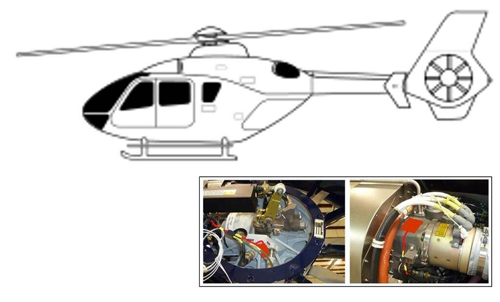
Heli-Preheat System – Airbus (Eurocopter) H135 (EC135 P1 & P2 & P3) with Pratt & Whitney PW206B/PW206B3
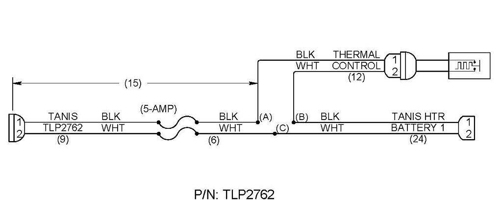
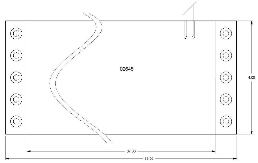
Preheat is supplied through electrical resistance elements in the form of thin pads sized and shaped to fit engine, main & tail rotor gearboxes, and oil tanks. Power is routed to the elements through a dedicated wiring assembly with circuit overload protection and power indicator light. System is self-regulating through design. Heated components reach an average state of thermal equilibrium in approximately six hours.
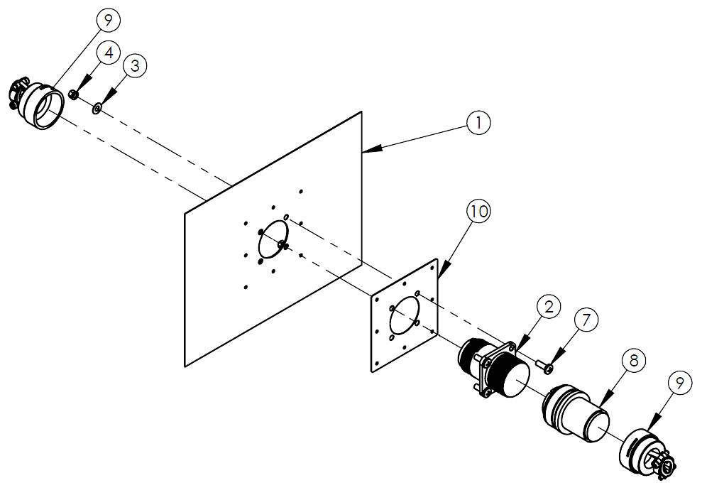
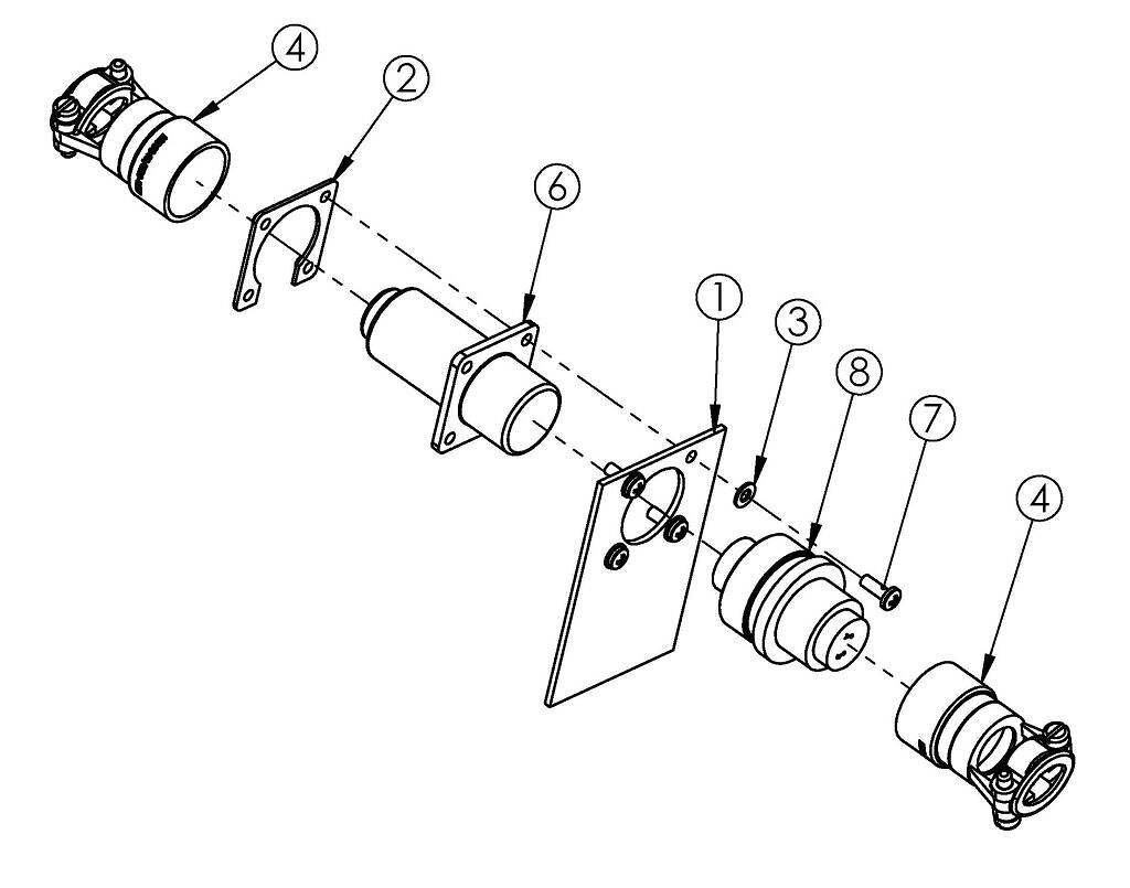
Firewall and Tail boom disconnection kits included.
This preheat kit when installed will supply 725 watts with a 6.3 amp draw at 115 volts.
Battery heat sold separately.
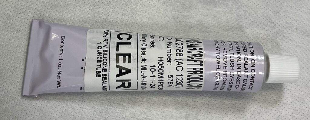
* Required Bonding sealant sold separately. Quantity 3, PN: TAU02788
* RTB0001 form required for purchase.
System not eligible for form 8130-3.
Additional Information
Heil Manufacturer: Airbus (Eurocopter)
Helicopter Cylinders: N/A
Engine Manufacturer: Pratt & Whitney
Old Part Number: TAS300-25-DT-115, TSHEC135-2230-115, TSHEC135-2230-115
Voltage: 115
USA-Cert (8130-3 available): RTB (NO)
Downloads
To access any of our Downloads (Documents) below, you will need to login or register for an account.
-
Drawing - Kit (System)
- 2230-115, System Kit Drawing for EC135 with PW206 534.85 KB
-
System Install Instructions
- TNH2230, EC135 Install Instruction with PW206 680.28 KB
-
Operator's guide
- TPG0003, Operating Guide for Turbine Rotorcraft (RFMS) (OM300) 320.04 KB
-
ICA (Instructions for Continued Airworthiness)
- TCA0003, ICA for Rotorcraft (all) 359.84 KB
-
Component Install Instructions
- TN01056, Fire Proof Grommet Install Instructions 107.07 KB
- TN02070, Flush Mount Plug Install Instructions 214.03 KB
- TN02782, Click Bond Mount Install Instructions 381.67 KB
- TN02788, Bonding of Pad Element Install Instructions (was 186) 121.86 KB
- TN02793, Instruction for DT series connectors (was 192) 329.80 KB
- TN02840, Single Place Plug Door Install Instruction 227.65 KB
- TN03039, LED Indicator Light Install Instructions 101.52 KB
-
Component Install/Mod Drawing
- 03030, Connector Kit Drawing/Installation Instruction (14 contact) 317.17 KB
- 03047, Connector Kit Drawing/Installation Instruction (2 contact) 351.43 KB
-
Drawing - Cable Kit/Wire Diagram
- 02764, Cable Kit Drawing for EC135 163.63 KB
-
Forms
- RTB0001, Request To Build – Fillable Form 203.46 KB